1.2/1.4TSI 4 Silindir Benzinli Motor
Audi A1, A3, Q3, Volkswagen Golf VII, Passat, SV, Sportsvan, Polo, Jetta, Seat, Leon, Leon ST, and Skoda Octavia III, Fabia III from
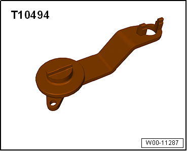
OEM T10494
Uyumlu Motor lar 1.2 / 1.4 Audi A1/A1 Sportback TSFI 2012'den 2015 CJZA CZCA A3 Cabrio g-tron
CYVB CXSB A3 Saloon CJZB CMBA A3/A3 Sportback
CYVA CXSA Q3 CJZC CPWA Seat Leon TSI TSI CJZD CHPB Leon ST LPG CYVD CHPA TGI CUKB Skoda Fabia III CNG CRJA Fabia III Estate CUKC Octavia III CZDA Volkswagen Golf VII GTE CPVA Jetta Hybrid CPVB Passat TSI MultiFuel Golf SV/Sportsvan TSI BlueMotion Golf VII Golf VII Estate Golf VII Wagon Golf SV/Sportsvan Golf VI Cabrio Golf VII Estate Golf VII Wagon Polo


| Special tools and workshop equipment required |
| Counterhold -T10172- with adapter -T10172/1- |
| Special wrench, 30 mm -T10499- |
| Insert tool, 13 mm -T10500- |
| – |
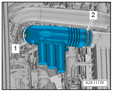
Loosen hose clips -1, 2- and remove air pipe. |
|
|
|
| – |
Move air hoses clear at air pipe. |
| – |
Detach connector from charge pressure sender -GX26-. |
|
|
|
| – |
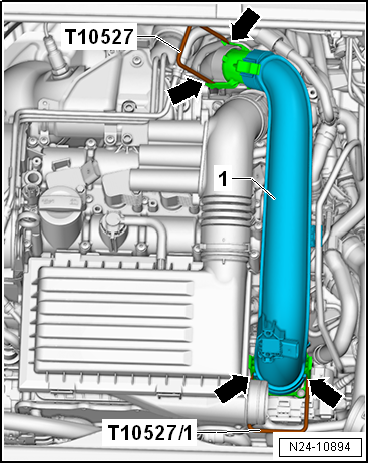
Release fasteners -arrows- using release tools -T10527- and -T10527/1-. |
|
|
 |
| – |
Press release buttons and pull off hose -1-. |
| – |
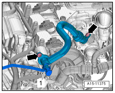
Remove bolts -arrows- and detach crankcase breather hose. |
| – |
Remove noise insulation → General body repairs, exterior; Rep. gr.66. |
| – |
Drain coolant → Chapter. |
|
|
|
| – |
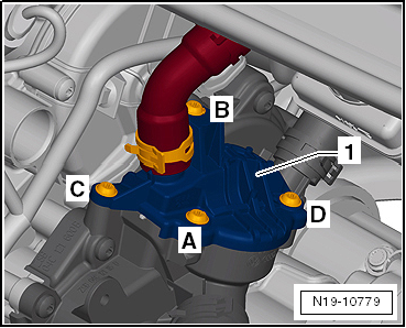
Unscrew bolts -A ... D-, and push cover -1- for thermostat to one side. |
|
|
|
| – |
Lay wiring harness to one side -arrows-. |
| – |
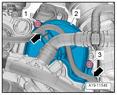
Unscrew bolts -1, 3- and remove cover -2- for toothed belt for coolant pump. |
|
|
|
| – |
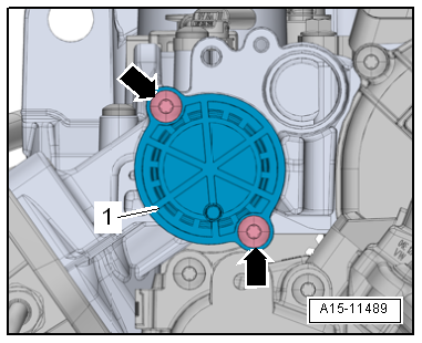
Unscrew bolts -arrows- and detach sealing cap -1-. |
| – |
Separate plug-in connectors from fuel hose and from hose to activated charcoal filter → Rep. gr.20. |
| – |
Release hoses from retainer -3- and lay them to one side. |
|
|
|
| – |
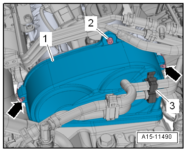
Release clips -arrows- and detach upper toothed belt guard -1-. |
 Note Note
| Place a cloth under the camshaft adjuster and tensioning roller to catch the engine oil which runs out. |
| The contact points between the toothed belt and components such as camshaft pulleys, crankshaft pulley, tensioning roller and idler pulley must be free of oil. |
|
|
|
| – |
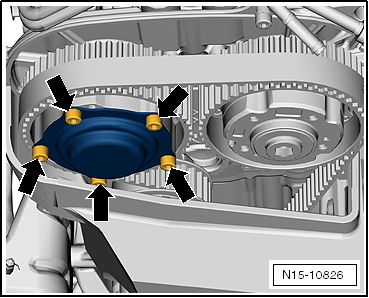
Unscrew bolts -arrows- and remove cover from camshaft adjuster for exhaust camshaft. |
| Rotate crankshaft to “TDC” as follows: |
| – |
Remove ignition coil 1 with output stage -N70- and cylinder 1 spark plug → Chapter. |
| – |
Insert a screwdriver with a shaft length of at least 250 mm into spark plug hole so that it contact piston crown. |
| – |
Turn the crankshaft in the normal direction of rotation until the piston in cylinder 1 shows “BDC”. |
|
|
|
| The screwdriver moves in the -direction of the arrow-. |
|
|

|
| – |
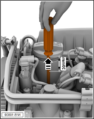
Turn the crankshaft further, until the screwdriver has moved -30 mm- in the -direction of the arrows- |
|
|
|
| – |
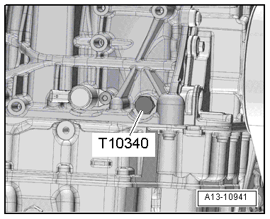
Unscrew plug for “TDC” hole in cylinder block. |
| – |
Screw locking pin -T10340- into cylinder block as far as stop and tighten to 30 Nm. |
| – |
Rotate crankshaft in normal direction of rotation as far as stop. |
| The locking pin now rests against the crank web. |
 Note Note
| Locking pin -T10340- locks crankshaft in direction of engine rotation only. |
| If locking pin -T10340- cannot be screwed in as far as stop, this indicates that crankshaft is not in the correct position! |
| In this case, proceed as follows: |
| Turn crankshaft 90° in direction of engine rotation. |
| Screw locking pin -T10340- into cylinder block as far as stop and tighten to 30 Nm. |
| Turn crankshaft in direction of engine rotation as far as stop. |
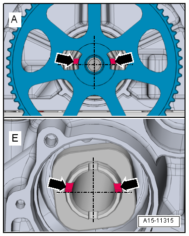
| On both camshafts on gearbox end the asymmetrical grooves -arrows- must be positioned right above horizontal camshaft centre line as shown in illustration. |
|
|
|
| The grooves on the exhaust camshaft -upper arrows- can be accessed through the recesses in toothed belt pulley for coolant pump. |
| On the inlet camshaft the grooves -lower arrows- must also be positioned right above horizontal camshaft centre line. |
| – |
If camshafts are not positioned as described, unscrew locking pin -T10340-, turn crankshaft one rotation further and return to “TDC” position. |
 Note Note
| The camshaft clamp -T10494- must slide into position easily. |
| Do not knock camshaft clamp into place with any kind of tool. |
| If the camshaft clamp -T10494- does not easily slide into position: |
|
|
|
| – |
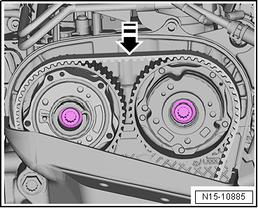
Use assembly tool -T10487- to push against toothed belt in -direction of arrow-. |
|
|
|
| – |
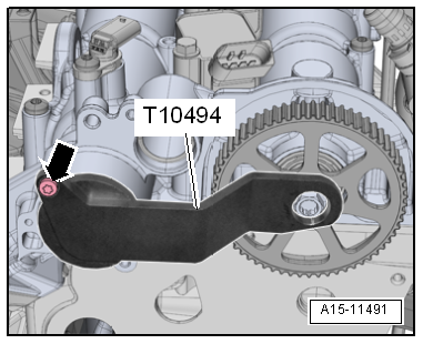
Insert camshaft clamp -T10494- as far as stop into camshaft. |
| – |
Tighten bolt -arrow- by hand. |
|
|
|
| – |
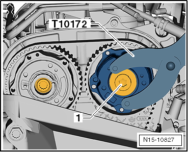
Unscrew plug -1- on camshaft sprocket on intake side using counterhold -T10172- with adapter -T10172/1-. |
Risk of damage to camshaft caused by improper handling.Never use the camshaft clamp for counterholding. |
|
|
| – |
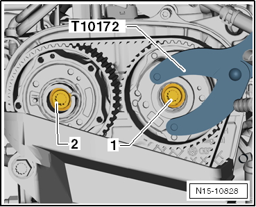
Loosen bolts -1, 2- approx. 1 turn using counterhold -T10172- with adapter -T10172/1-. |
|
|
|
| – |
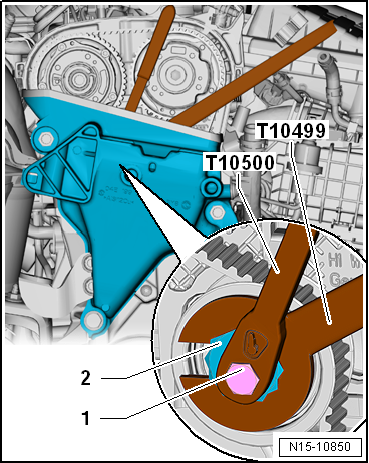
Loosen bolt -1- with tool insert -T10500-. |
| – |
Release tensioning roller on eccentric adjuster -2- using special wrench, 30 mm -T10499-. |
| Risk of damage to the toothed belt. |
| The toothed belt is made of glass fibre fabric. |
| Therefore, bends in the toothed belt must not be smaller than 50 mm in diameter. |
| Otherwise the service life of the toothed belt will be reduced. |
| – |
Remove toothed belt from camshaft pulleys. |
| Installing (adjusting valve timing) |
 Note Note
| Renew bolts that are tightened with specified tightening angle. |
| Renew O-ring of plug if damaged. |
| – |
Check “TDC” position of camshaft and crankshaft: |
|
|
|
| Camshaft clamp -T10494- must be attached to camshaft housing. |
Risk of damage to camshaft caused by improper handling.Never use the camshaft clamp for counterholding. |
|

|
| Locking pin -T10340- screwed into cylinder block as far as stop and tightened to 30 Nm. |
| Crankshaft has been turned in direction of engine rotation until it rests against locking pin -T10340- = “TDC” position. |
|
|

|
| – |
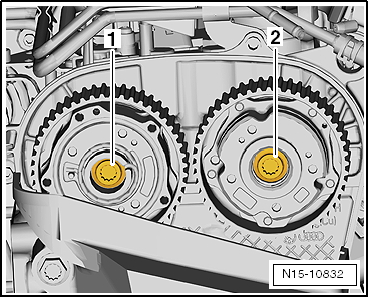
Renew bolts -1- and -2- for camshaft pulleys and screw them in loosely. |
| It should just be possible to turn the adjusters on the camshafts but no rocking is permissible. |
|
|
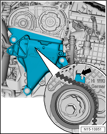
|
| The sheet-metal tab -arrow- of the tensioning roller must engage in the cast notch of the cylinder head. |
| Risk of damage to the toothed belt. |
| The toothed belt is made of glass fibre fabric. |
| Therefore, bends in the toothed belt must not be smaller than 50 mm in diameter. |
| Otherwise the service life of the toothed belt will be reduced. |
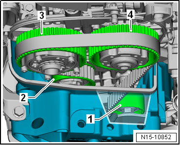
| Fit toothed belt in prescribed sequence: |
|
|
|
| – |
Pull toothed belt upwards and fit it on idler pulley -1-, tensioning roller -2- and camshaft toothed belt pulleys-3- and -4-. |
|
|
|
| – |
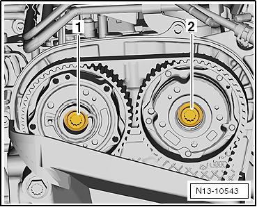
Tighten bolts -1, 2- initially to 50 Nm using counterhold -T10172- with adapter -T10172/1-. |
|
|
|
| – |
Unscrew locking pin -T10340-. |
|
|

|
| – |
Remove bolt -arrow- and detach camshaft clamp -T10494-. |
|
|

|
| – |
Turn crankshaft 2 turns in direction of rotation of engine. |
| – |
Screw locking pin -T10340- into cylinder block as far as stop and tighten to 30 Nm. |
| – |
Rotate crankshaft further in direction of engine rotation as far as stop. |
| The locking pin now rests against the crank web. |
 Note Note
| Locking pin -T10340- locks crankshaft in direction of engine rotation only. |
| – |
It should be possible to insert the camshaft clamp -T10494- easily. |
| Do not knock camshaft clamp into place with any kind of tool. |
| If the camshaft clamp -T10494- does not easily slide into position: |
|
|

|
| – |
Use assembly tool -T10487- to push against toothed belt in -direction of arrow-. |
|
|

|
| – |
While doing this, insert camshaft clamp -T10494- into camshafts as far as stop and hand-tighten with bolt -arrow-. |
| If it is not possible to insert camshaft clamp -T10494-, the valve timing is not correct. |
| – |
Repeat adjustment of valve timing. |
| If it is possible to insert camshaft clamp -T10494-, the valve timing is correct. |
|
|

|
| – |
Unscrew locking pin -T10340-. |
|
|

|
| – |
Remove bolt -arrow- and detach camshaft clamp -T10494-. |
| – |
Tighten bolts -1- and -2- to final torque setting → Chapter. |
|
|

|
| – |
Use counterhold -T10172- with adapter -T10172/1-. |
|
|

|
| – |
Tighten plug -1- using counterhold -T10172- with adapter -T10172/1-. |
| After completing work, check that locking pin -T10340- and camshaft clamp -T10504- have been removed. |
| Further assembly is carried out in the reverse order of removal. |
| → Chapter „Assembly overview - toothed belt“ |
| → Fig. „“Plug for TDC drilling in cylinder block - specified torque”“ |
| → Chapter „Assembly overview - camshaft housing, engine codes CHPA, CMBA, CPVA, CXSA, CZCA, CPVB, CZDA“ |
| → Chapter „Assembly overview - crankcase breather system“ |
| → Chapter „Assembly overview - coolant pump, thermostat“ |
| → Chapter „Assembly overview - charge air system“ |
|